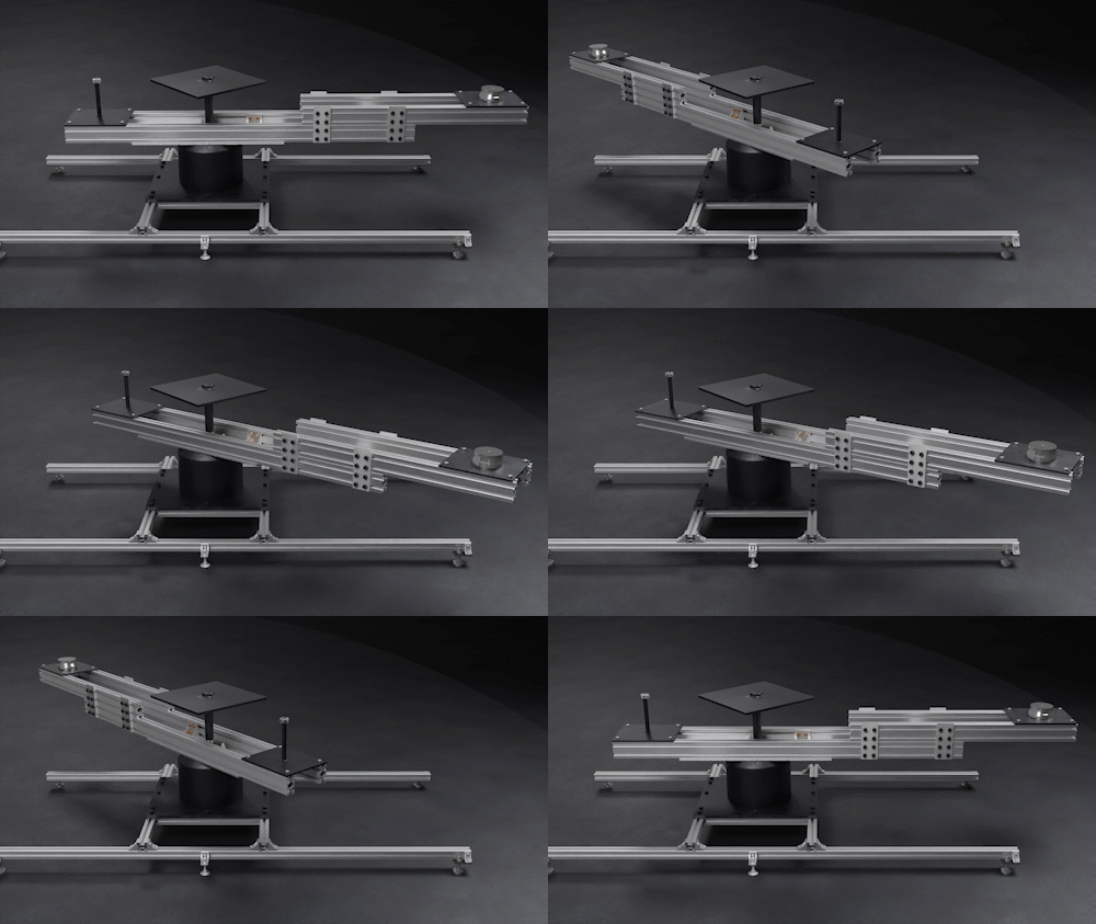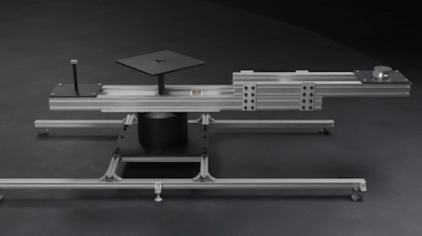
The RIG CAMERA 360° is for extremely heavy items:
Up to 350Kg
Rotation speed up to: 180°/s
Movable design
Controlled by a programmable box or handwheel
Link installation guide: https://youtu.be/h4BZIA0DaGg
Step 1.1: Start by lowering the four pedestal legs of the rotating table to create a stable foundation and ensure precise leveling. Use a leveling tool or measurement guide to ensure each leg is lowered to the same level. This step is crucial to prevent any imbalance or instability in the table after installation.


Step 1.2: Next, lower the two central legs to further enhance the stability of the rotating table. Adjust their height carefully to augment the table's overall balance.


Step 2.1: Before installation, you'll have three choices regarding the size of the spindle connecting the rotating table: small, medium, and long. Determine the appropriate size based on your specific requirements.
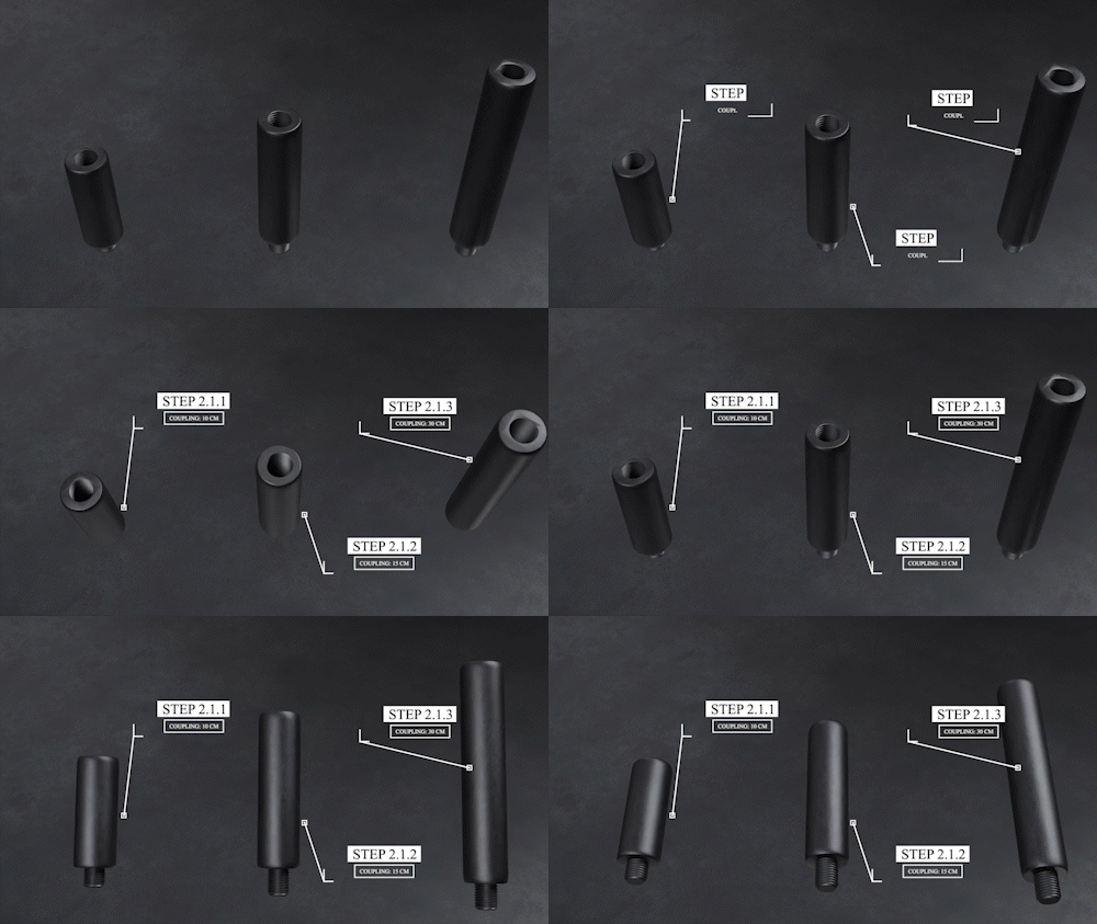

Step 2.2: Once you've chosen the suitable size, proceed to install the spindle onto the rotating table. Follow the manufacturer's instructions precisely to ensure safe and efficient installation.


Step 3: Subsequently, assemble the rotating table's spindle according to the provided guidelines. Ensure a secure and accurate assembly to avoid any operational issues.


Step 4: After completing the installation, write the necessary operational commands to run the rotating table as per your specific job requirements. Thoroughly test its functionalities to ensure proper operation.


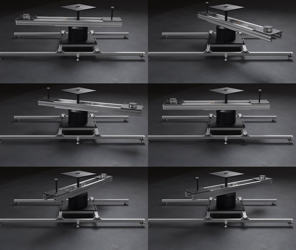
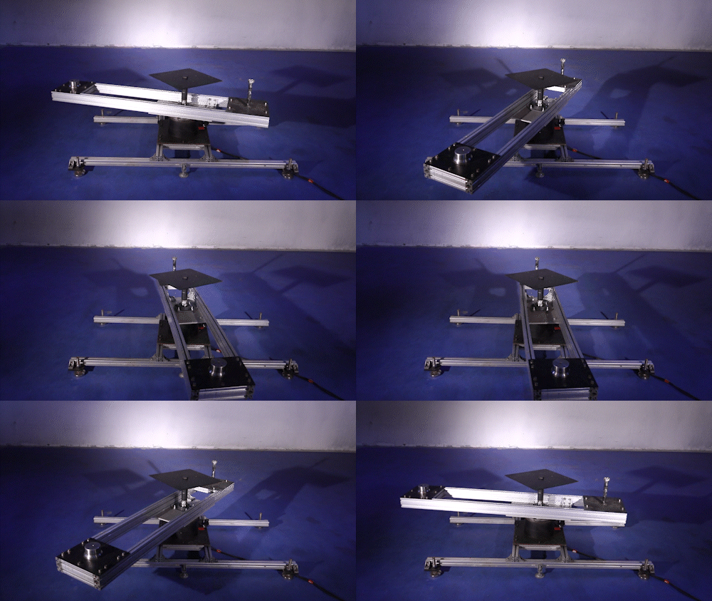
To expand the cam width and make necessary adjustments:
Step 5: Disassemble the current cam attachment from the rotating table, handling this process with caution to prevent any damage

Step 6: Proceed to attach the intermediary pass between the two joints, encompassing all four passes for enhanced stability and functionality of the cam.

Step 7: Use shaped aluminum to link the upper pass to the lower-shaped aluminum pass, creating a robust and reliable connection.

Step 8: Tighten the screws securely between the two passes to ensure a stable connection and safety.
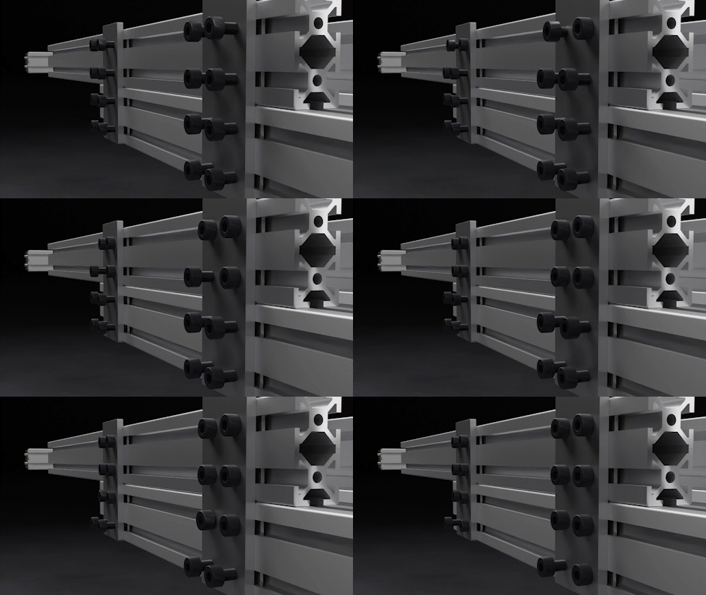
Step 9: Finally, reattach the cam pass on the upper side of the intermediate joint to complete the process of expanding the cam width.
